Summary:
This post is explaining how I modified my roaster to control my roast profile using the BT curve (Bean Temperature) instead of the ET curve (Environment Temperature) using a Fuji PXF PID controller and the state of the art roasting software Artisan-Scope.
Background:
In my previous post, I explained how I integrated a Fuji PXF PID to control my coffee roaster’s ET (Environment Temperature) temperature.
Controlling the hot air temperature and the environment temperature has significantly improved my roasts.
But at the same time, controlling the environment temperature will not always give the same BT (Bean Temperature) when some of the external parameters are changing (Roaster pre-heat, batch size, green coffee batch, external “room” temperature…).
It is also not a straightforward approach if you want to redesign an existing roasting recipe to a new duration or change the batch size.
I knew that I could improve this but didn’t quite know how to start, what was the best approach.
What I knew I wanted was:
- To be able to design a BT curve in the Artisan Designer
- Have my roaster follow this BT curve no matter what external parameter I was starting with….
I had seen my people do this successfully, but I needed to better understand how to re-wire the electronic part of the roaster and configure Artisan accordingly.
I also knew that it would be more than a couple of hours, which meant that once I would start, I would not be able to roast until it would be completed and working.
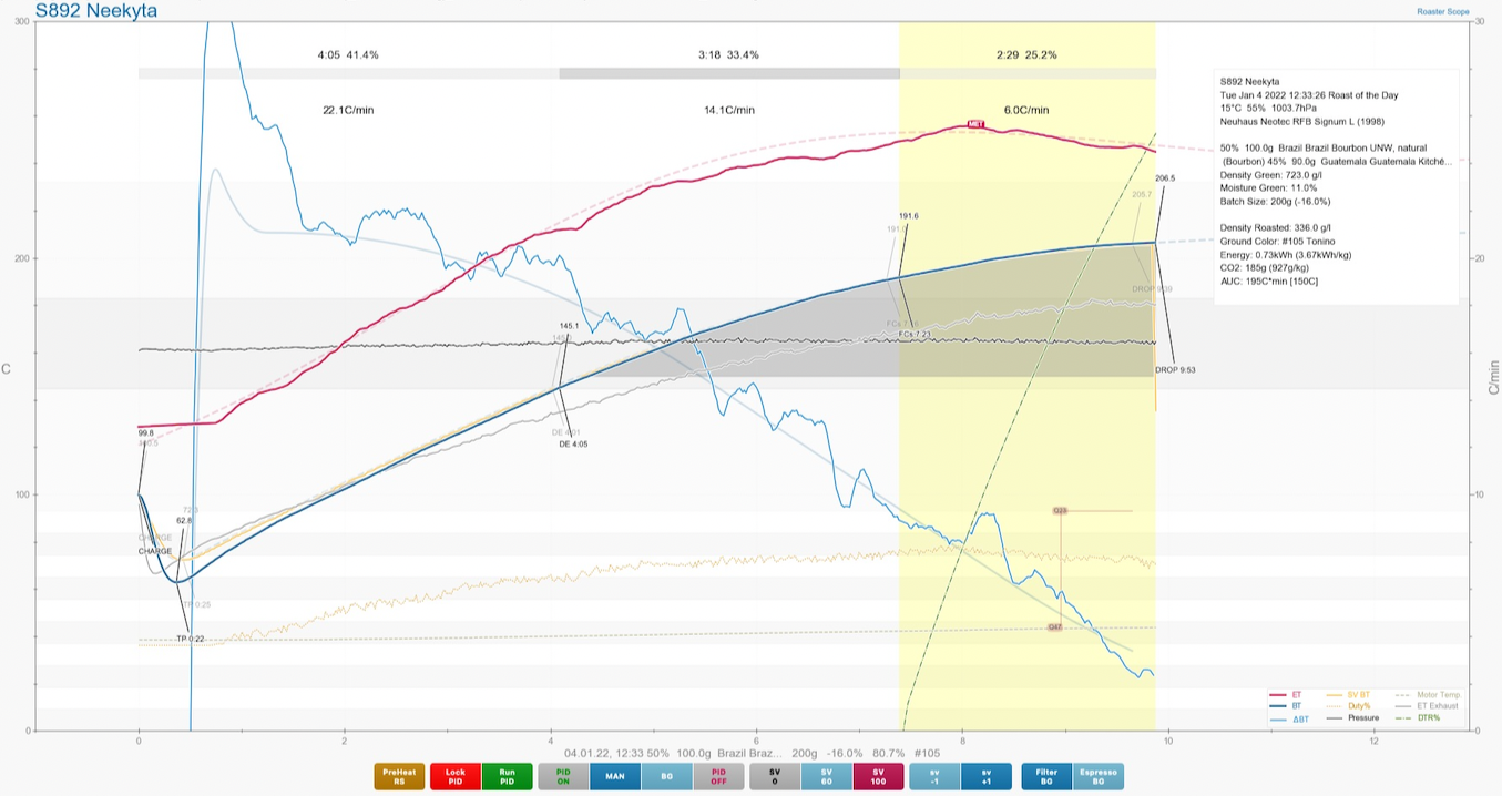
Below is an example of my one of my roasting profilesusing the PID to control the ET value. everything was already quite smooth:
While there is nothing new here, many have done the same before me (see the full list of links below, at the end), this post is explaining how I did it on my hot air roaster (Neuhaus RFB Signum L) using the Fuji PXF PID.
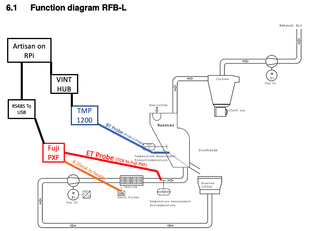
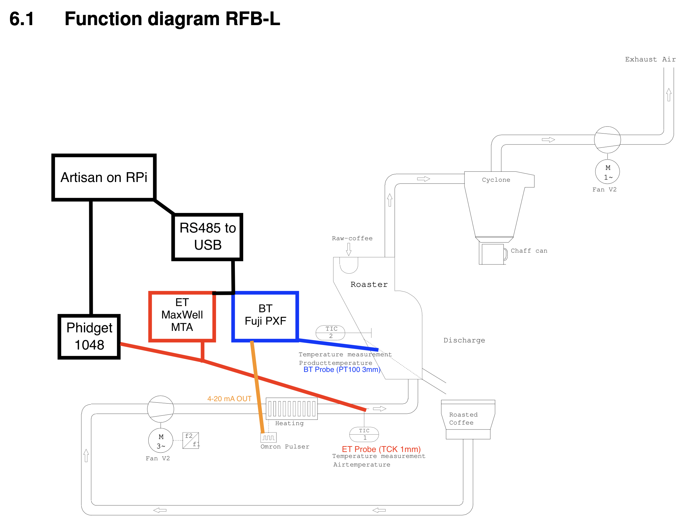
As a starting point, to help others better understanding my explanations, here is below a simplified schematics of my Roaster and Artisan integration before this post (more pictures at the end of the post):
Preparation:
I started by roasting many batches to have enough coffee for my wife and used some of the spare time during the Christmas break.
As in most cases, the best approach when not knowing how to tackle a problem, is to ask other users who did it in the past for support.
The discussion on Github can be found here: https://github.com/artisan-roaster-scope/artisan/discussions/763
Basically, the outcome of the Artisan-Scope Github discussion and offline discussion with some users was that I needed to rewire the input of the Fuji PXF PID.
Instead of using the Air temperature probe (ET) placed right after the heater I needed to connect the Bean Temperature (BT) probe which is placed in the coffee bean pile in the roasting chamber.
Safety note:
One additional note on roaster safety (and your own safety) when doing this type of modification.
If not being careful and not using the right PID configuration, as the regulating probe is now placed significantly further from the heater/burner, you could quite quickly overheat the heater as it would go to maximum power until reaching the desired BT temperature.
Some heaters or roasters may not have any protections and you may damage the roaster.
During all the tests, I always had a live reading of my air temperature probe (placed directly after the heating element) and was ready to stop the heater manually if required.
Always anticipate what could happen, just in case...
Starting the modifications here:
- I connected by PT100 probe to the Fuji PXF which was previously connected to the ET thermocouple type K
- I connected the Thermocouple Type K (TCK) used for ET to the old MaxWell MTA PID and to the Phidget 1048 (See previous post on the MaxWell, not very good at regulating when using variable SV, but it is fine as a display or for static SV)
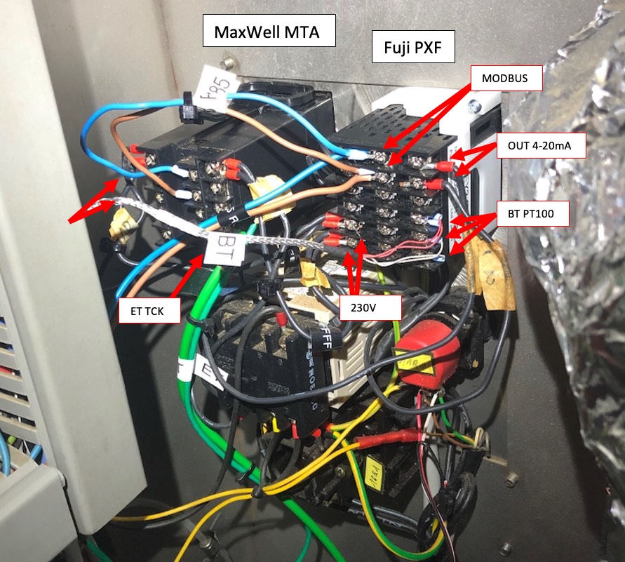
The back of the PIDs
The updated simplified schematics is now as described below:
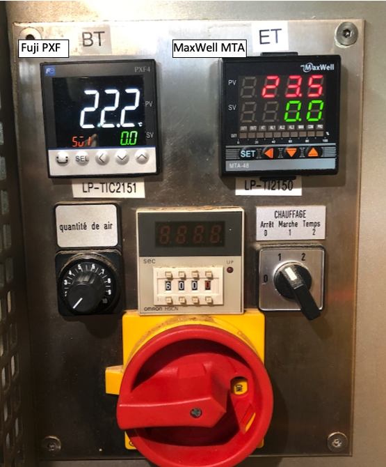
The front panel with the 2 PIDs
The configuration in Artisan: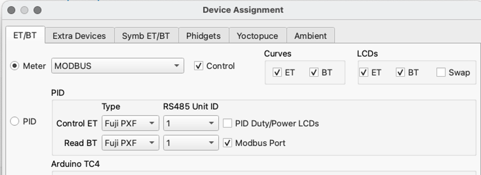
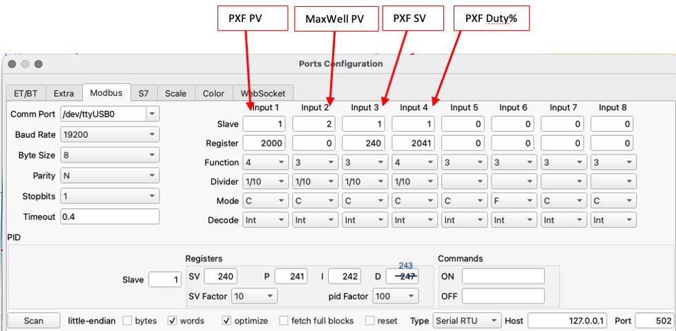
Modbus configuration (update 03.03.2023: PID "D" value register corrected in screenshot):
Extra devices configuration: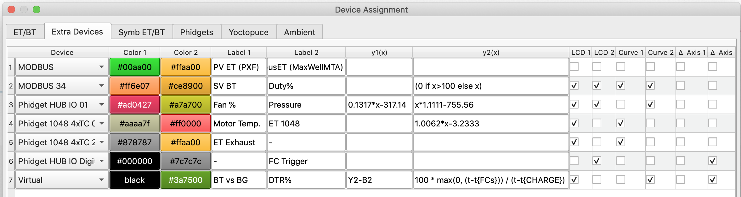
and the Symbolic assignments for ET/BT: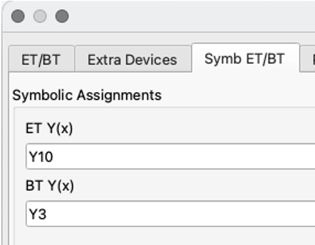
Due to my roaster setup, I had of course to change the Fuji PXF configuration from TCK to RTD (and also had to reconfigure some PXF settings as my SV was not aligned anymore in between Artisan and the PXF).
Once connected, I ran the Autotune function of the Fuji PXF with some green beans in the roast chamber. Once I had a roughly adjusted PID, I reloaded new green beans (using the same quantity as I generally use), started a profile and once I was mid-way, stabilized at 160°C and ran the autotune again:
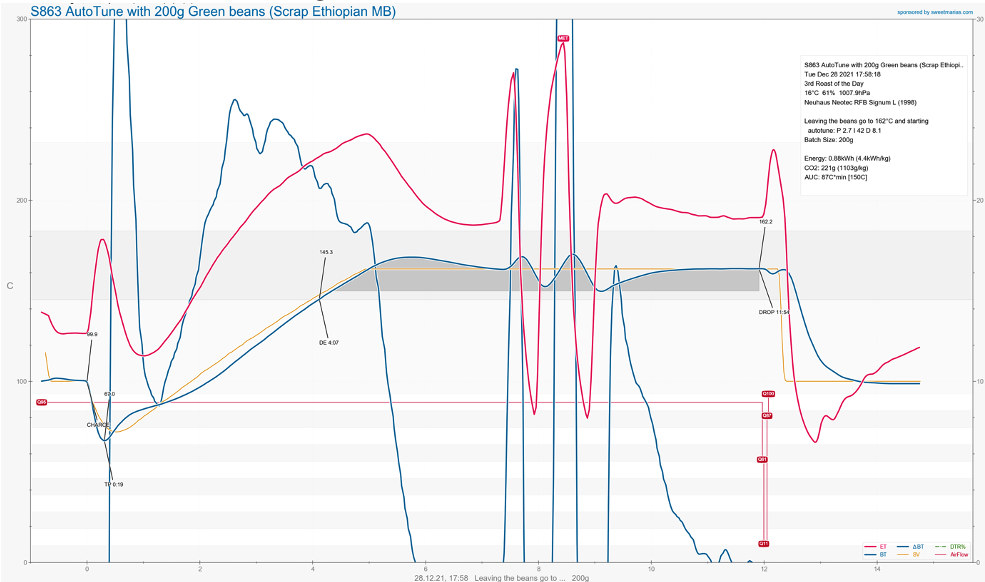
The resulting PID settings were P: 2.7, I: 42, D: 8.1 which in Artisan are for me P: 0.27, I: 4.2 and D: 8.1:
I then loaded green beans with the new settings and started the profile: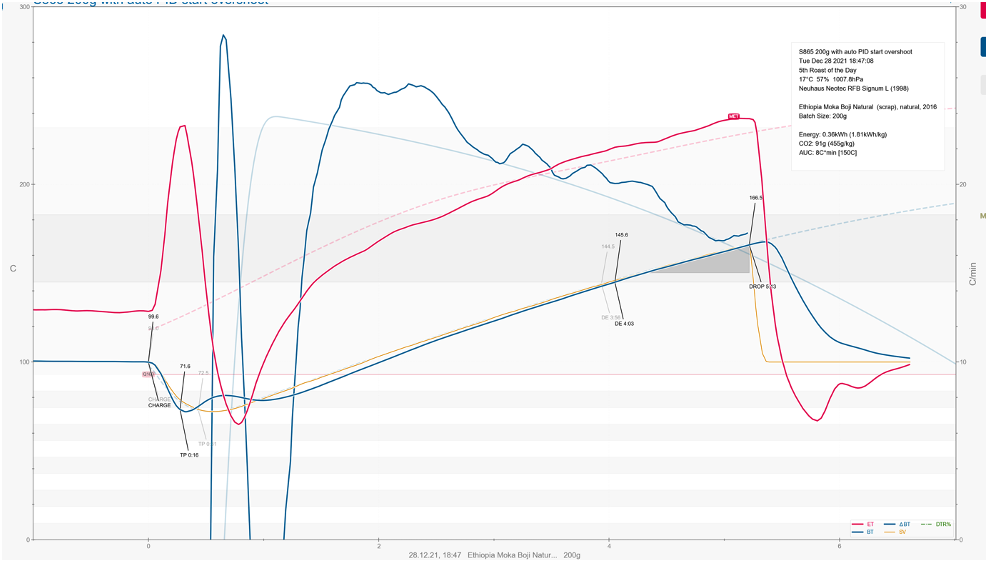
There was quite a nasty ET overshoot at charge, but afterward, most of the curve was close to what I wanted to achieve.
So I tried again with a lower charge temperature, changing my BG designer template, changing P,I, D values at charge.
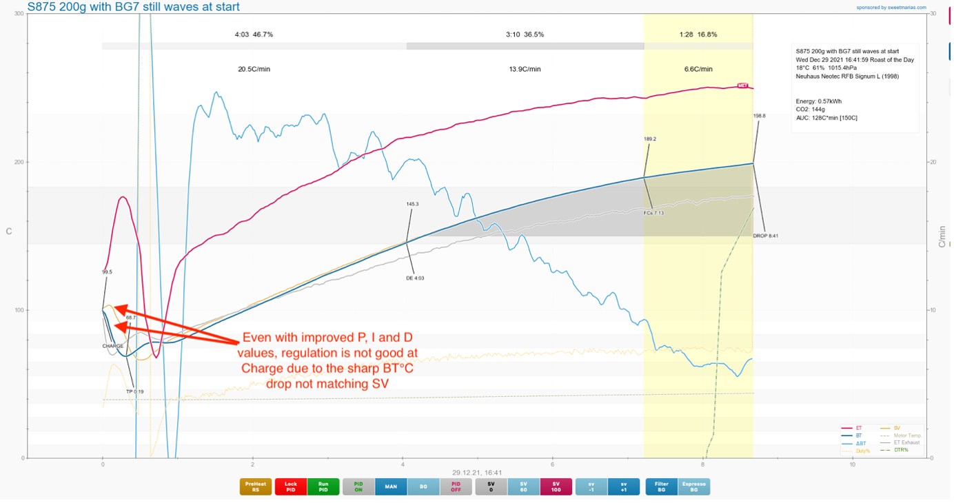
There was still a large ET (red curve) overshoot due to the fact that BT (blue curve) is generally always different from SV (orange curve) during the high variations around the CHARGE event.
Even by improving the background curve, it is hard to be precise and many external factors will influence this part.
Initially I thought I would need to find different P, I and D value to avoid the overshoot at CHARGE.
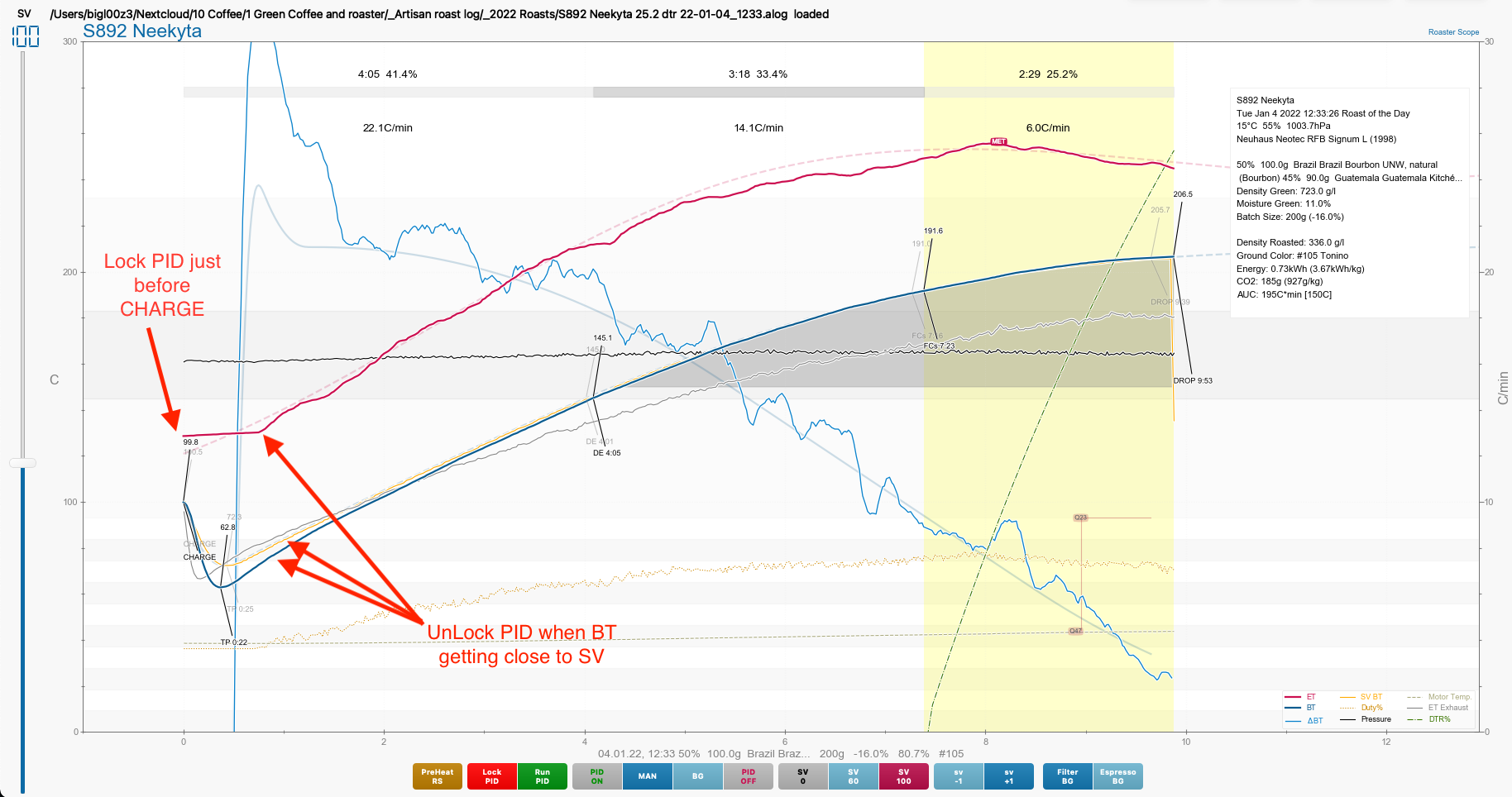
But in the end, a much better approach was to send a command to the Fuji PXF just before CHARGE to lock the PID (which means it will freeze at the current values which works very well if the roaster has been preheated and is in stable conditions).
This approach is not new and is based on various examples. One of them found in this post by Loring roasters. In the "Before Turn Around Point (TAP)" and the "After Turn Around Point (TAP)" sections of the article, the PID is changed to an "Open Loop" state and then back to a "Closed Loop" state after the turning point.
(Open/ Closed loop explanation here."The main difference between an open-loop system and a closed-loop system is that the closed-loop system has the ability to self-correct while the open-loop system doesn't. Consequently, closed-loop systems are often called feedback control systems while open-loop systems are also known as non-feedback controls." ).
So back to our case, after the Turning Point, when the BT value is getting closer to the SV value, the Fuji PXF is unlocked.
On the Fuji PXF, I do this by setting it to "Manual" mode using the MODBUS command write(1,132,1) and then back to Auto mode using the command write(1,132,0).
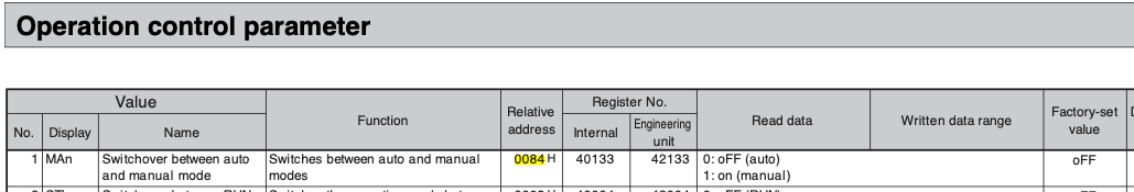
From the Fuji PXF MODBUS Manual: I use the register 0084H which is 132 in Decimal mode (to convert from HEX to Decimal, you can use one of the online converter).
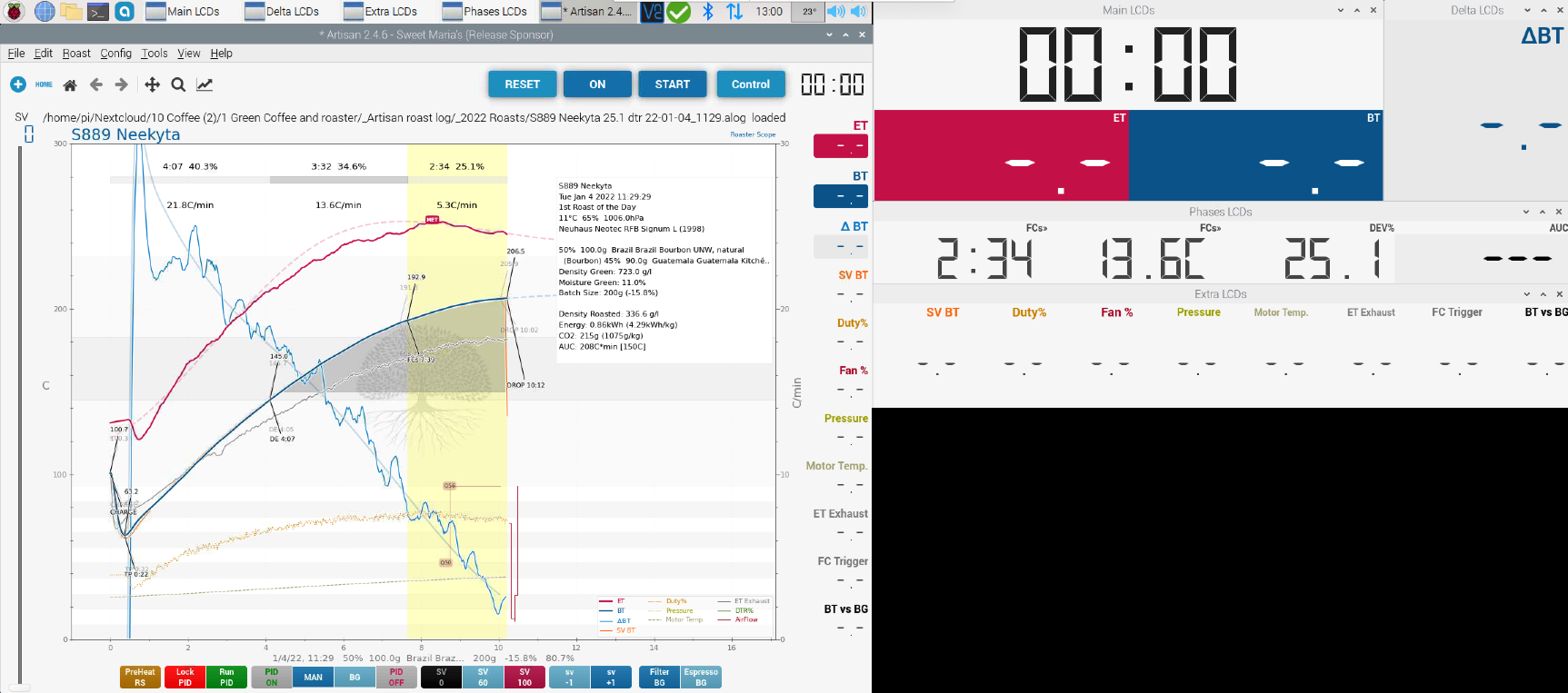
The resulting curve is just beautiful. ET is constantly being fined tuned to have BT follow the BT background curve:
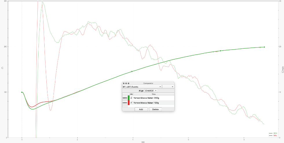
I have tried to roast a full batch size (200g) and half batch size (100g) with the same DTR%.
While there is a slight BT bump at start (expected), I (as expected) got very similar profiles. Tonino Roast colour was at 1 point difference in between the 2 batches (Tonino 119 and 118):
Preheating:
In the past I would preheat the roaster by just sending a SV temperature (e.g. 150°C) until warm enough.
With the new setup, this generally results in a major ET overhoot which can go over 300°C. This could potentially be a safety issue for the roaster (hopefully the heating element is selfprotecting itself, but I don't want to try).
While I could set P, I and D value to have a shorter ramp up during the preheat cycle, I found that it was better using the RAMP/SOAK function with the same P, I and D values.
My current RAMP/SOAK configuration is:
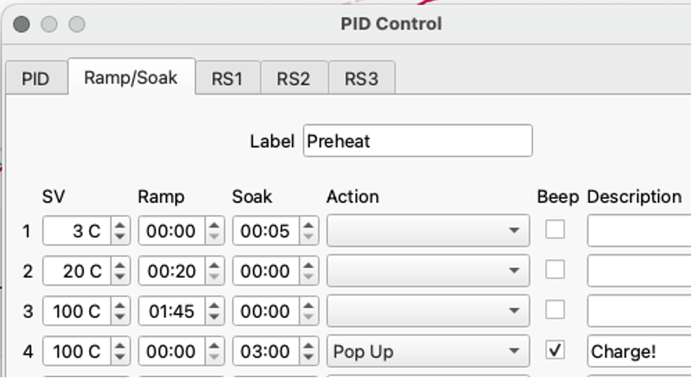
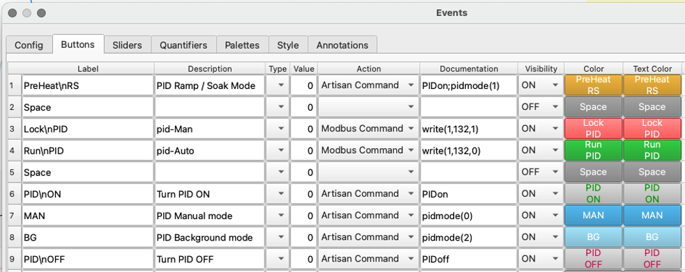
And is linked to a button:

With the following button configuration:
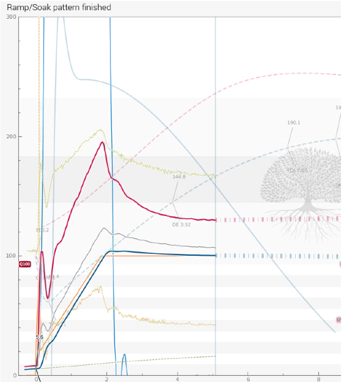
The Preheat cycle looks like this:
Conclusion:
I am now a happy roaster, feeling much more in control of my curves…
…and my wife has great coffee to drink.
As usual, a big thank you to the Artisan-Scope community for supporting each other and supporting the software (by the way you can make donations to Artisan here)
Related links:
Below are a few references to other people’s PID implantations who clearly inspired or supported what I did. All the credits to them:
- Artisan-Scope: PID
https://artisan-scope.org/devices/pid/ - Marko Luther: PID Control
https://artisan-roasterscope.blogspot.com/2016/11/pid-control.html - Jason Scott: Using PID to control the heat of a coffee roast in Artisan software
https://youtu.be/5OrrdhCTBPE - CK : Artisan Scope Automated Roast
https://youtu.be/Jjh738sJGBI - Frans Goddijn’s many PID posts:
http://kostverlorenvaart.blogspot.com/2016/08/first-successful-curve-controlled-fz-94.html
http://kostverlorenvaart.blogspot.com/2014/01/new-pid-plans-for-fracino-roastilino.html
http://kostverlorenvaart.blogspot.com/2014/01/fuji-pxg4-setup-for-coffee-roasting.html
http://kostverlorenvaart.blogspot.com/2017/02/artisan-adding-fuji-pxg4-pid-to-coffee.html
http://kostverlorenvaart.blogspot.com/2016/02/curve-controlled-coffee-roasting.html - Virtual Coffee Lab : Roasting Coffee with Artisan Data Logging Software
https://youtu.be/1qNyp6DONgk - Loring:
https://loring.com/pid-coffee-roaster-explained/
and many more...
Additional setup pictures :
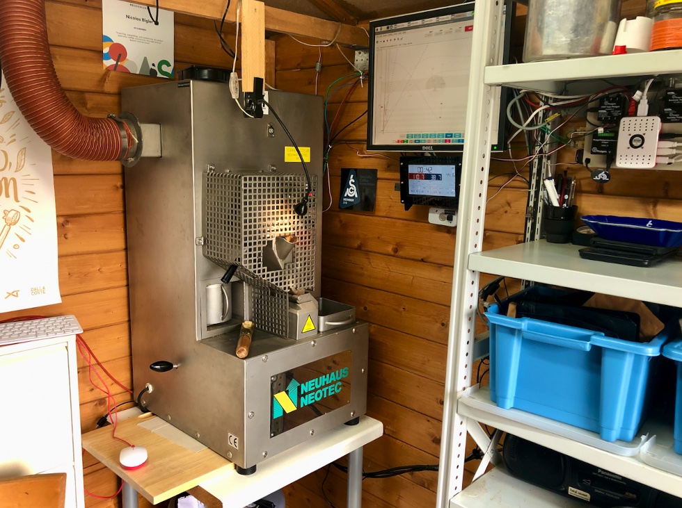
The roaster
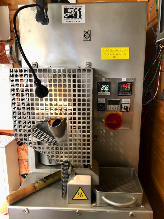
Front panel
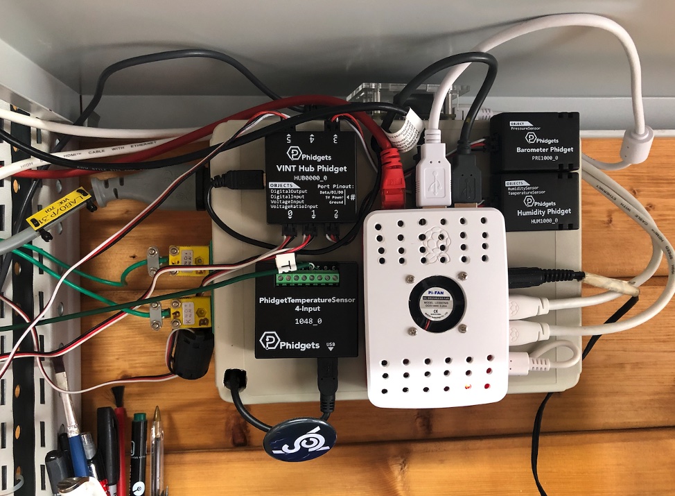
The Raspberry Pi and the Phidgets brain (only part of the Phidgets)
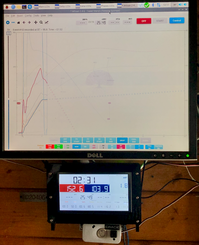
The 2 monitors with Artisan-Scope and the First crack Button below the smaller monitor.
Better view of the displays layout